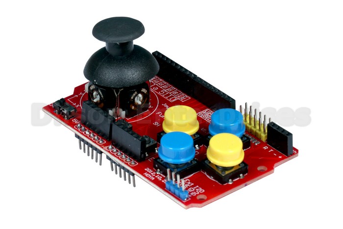
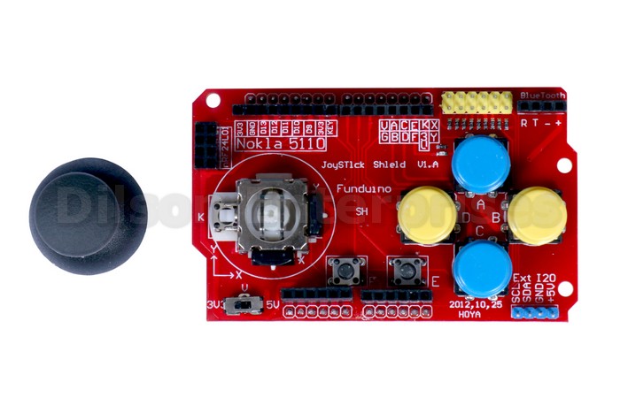
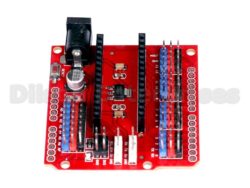
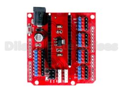
Joystick Protect Module
Features: JoyStick Shield Module Robotics Control
- NRF24L01 RF interface.
- For Nokia 5110 LCD interface.
- Bluetooth interface I2C interface.
- for one PS2 joystick.
- 2-Axis joystick.
- Bluetooth / Serial interface.
- I2C interface.
- NRF24L01 interface.
- Nokia 5110 LCD interface.
- Interface connector.
- Power switch to switch between 3.3 and 5V.
Specifications: JoyStick Shield Module Robotics Control
- Input Supply Voltage: 3.5~5V
- Color: Red
- Dimension Size: 87*53*30
- Weight: 37gm
14
People watching this product now!
Description
The Joystick V2.0 has added Nokia 5110 LCD and nRF24L01 interface.
You possibly can simply develop your Joystick video games, and even talk one another with wi-fi nRF24L01. These pinouts additionally helps it to simply get related to different processors which helps to develop an consumer pleasant setting.
The protect sits on high of your Arduino and turns it right into a easy controller. 7 momentary push buttons ( 4 large buttons + 2 small buttons + joystick choose button ) and a two-axis thumb joystick offers your Arduino performance on the extent of previous Nintendo controllers.
The Joystick v 2.0 with Nokia 5110 doesn’t assist normal Arduino board Due to normal Arduino board 3.3 v simply provide 50mA present, which might’t assist Nokia5110 backlight want.
This JoyStick Protect Module Robotics Management is an Uno appropriate protect that means that you can flip an Arduino Uno or appropriate right into a sport console or robotic controller. 3.3V to 5V Gamepad Joystick Protect Module Recreation Rocker Button Controller Enlargement Board For Arduino Simulated Keyboard Mouse Module.
The protect sits on high of your Arduino and turns it right into a easy controller. 7 momentary push buttons ( 4 large buttons + 2 small buttons + joystick choose button ) and a two-axis thumb joystick offers the Arduino performance on the extent of previous Nintendo controllers.
2-Axis Joystick:
The X-Axis potentiometer of the joystick is related to A0. The Y-Axis potentiometer is related to A1. The analog inputs on a microcontroller learn values over a spread of 0-1023 (for typical 10-bit ADC inputs). The X-Axis and Y-Axis controls ought to learn round 512 (midpoint) when the management is at relaxation. Because the joystick is moved, one or each of the controls will register larger or decrease values relying on how the management is being moved. The joystick additionally has a button ‘Ok’ which is activated by urgent the joystick down. This button is related to D8.
Buttons:
There are a complete of 6 buttons on the board (not together with the one on the joystick) labeled A-F. The 4 massive buttons are usually used for up/down/left/proper or comparable features. The 2 smaller buttons are usually used for much less generally used features equivalent to ‘choose’ or ‘begin’ since they’re much less accessible / much less prone to be pressed unintentionally. All buttons have pull-up resistors and pull to floor when pressed.
Button A – Connects to D2
Button B – Connects to D3
Button C – Connects to D4
Button D – Connects to D5
Button E – Connects to D6
Button F – Connects to D7
Bluetooth Connector:
The RX/TX traces are introduced out to a separate 4-pin feminine header together with 3.3V and Floor. This can be utilized for connecting a 4-pin 3.3V Bluetooth system or a TTL serial system.
I2C Connector:
The I2C SDA and SCL traces are introduced out to a separate 4-pin male header together with 5V and Floor. That is along with the traditional A4/A5 location of those traces. This enables for simple attachment of I2C units.
nRF24L01 Connector:
This connector permits a nRF24L01 RF transceiver module to be plugged in.
2 x 4 Feminine Header
GND – Floor
VCC – 3.3V
CE – Connects to D9
CSN – Connects to D10
SCK – Connects to D13
MOSI – Connects to D11
MISO – Connects to D12
IRQ – No Connection
Nokia 5110 LCD Connector:
This feminine header connector is designed to mount the Nokia 5110 LCD that was initially designed for Nokia telephones and offers a 48×84 pixel matrix.
This interface occupies the identical D9-D13 pins because the nRF24L01, so you possibly can’t use each on the similar time.
Interface Connector:
This twin row yellow male header connector offers one other level of entry to all of the buttons, joystick pots, 3.3V, 5V and Floor. The pin-out of this connector is labeled on the board to the left of the connector.


